
| RFC-0250: Power topology | |
|---|---|
| Status | Accepted |
| Areas |
|
| Description | Describes the model for interdependent state management to be used by system power management. |
| Issues | |
| Gerrit change | |
| Authors | |
| Reviewers | |
| Date submitted (year-month-day) | 2024-03-09 |
| Date reviewed (year-month-day) | 2024-06-03 |
Summary
One of the key problems of system power management is supporting the transitions of various system elements — a term we use plainly to refer to things with a state, hardware and software alike — to different states while properly managing interdependencies between those states. This proposal specifies a model called the Fuchsia Power Topology that can be implemented to solve this problem, while simultaneously offering solutions to related problems in attribution and observability. This work is focused on establishing a conceptual framework with rigorously-defined terminology; future RFCs will address designs more closely related to implementation.
Motivation
The state management problem
This proposal originates from the need to support system suspend/resume operations in Fuchsia, as described in RFC 230.
A major task of system suspension is ensuring that all hardware elements have been placed in the appropriate low-power states before the CPUs stop executing instructions. Superficially, this might seem like a dependency-management problem one layer deep: the "active" states of hardware elements depend on the active state of the CPUs, and so hardware elements must be taken to suspended states before CPUs are suspended.
However, hardware elements may depend on each other; for example, devices must be suspended before buses can be de-powered. Meanwhile, devices may have multiple states that are desirable to use during system suspension under different conditions, such as a low-power state that should be used if the device is to serve as a wake source and a fully-off state if it is not. Meanwhile, the associated state management problems are not isolated to system suspension. Hardware elements may be taken to low-power states while CPUs are active, such as when a phone is placed in airplane mode, requiring that certain radios be turned off.
These factors make it valuable to create a framework that supports transitions of interdependent states. As power management is the main reason such transitions are necessary, this responsibility falls to Fuchsia's Power Framework. We introduce the term "power topology" to somewhat flexibly refer to both the dependency graph at the heart of this framework and the framework itself.
In developing the power topology, we found that the concepts required to manage state dependencies between hardware elements extend naturally to software elements, which can provide higher-level abstractions on top of hardware or naturally describe the enabled/disabled state of user-facing features. In particular, by explicitly capturing the dependencies necessary to support user-facing features, we establish a natural means to enforce on-demand utilization such that dependencies are only utilized when needed, and to provide attribution of utilized resources to the features that require them. Attribution to components is of interest as well, but features are more closely tied to the reasons power is utilized and thus call for attribution at a sub-component level.
The concepts we establish to enforce demand-based state changes will allow the power topology to encode not only the states supported by elements across the system but the rules for driving state changes. This will create a powerful tool for product developers and systems engineers, who will be able to review systemwide behaviors and propose functional changes via the topology itself rather than source code.
Why a new topology?
Fuchsia already has two significant topologies used to describe drivers and components. However, neither of these readily accommodate solutions to the state management problem. As such, we develop the power topology in its own right, with the expectation that we will regularly revisit the component and driver graphs to clarify its role in relation to them.
For ease of reference, we briefly review the existing topologies.
The component topology describes two things: the parent/child relationships between component instances and the capability routing graph. It is a tree describing the hierarchy of component instances, and capabilities are mapped into a DAG on top of that tree. If a component needs access to a capability from another subtree, the capability is routed through its parent.
The driver manager also tracks its own node topology as a DAG. In the driver framework, a node is an abstraction of a device, and drivers bind to nodes to use their associated resources, such as access to MMIO registers. Drivers are components in the component topology, but they are flattened into collections. The reason for this structure is that the component topology does not have a way to represent nodes without a driver bound to them, and nodes may have multiple parents (these are called composite nodes) which is not allowed by the tree structure of the component topology.
Stakeholders
Facilitator:
Adam Barth abarth@google.com
Reviewers:
- Power: Kyle Gong kgong@google.com
- Power: Michael Brunson mbrunson@google.com
- Driver Framework: Justin Mattson jmatt@google.com
- Driver Framework: Harsha Priya NV harshanv@google.com
- Zircon Kernel: Nick Maniscalco maniscalco@google.com
- Platform Drivers: Andres Oportus andresoportus@google.com
- Component Framework: Gary Bressler geb@google.com
Consulted:
- David Gilhooley dgilhooley@google.com
- Corey Tabaka eieio@google.com
- Filip Filmar fmil@google.com
- Guocheng Wei guochengwei@google.com
- HanBin Yoon hanbinyoon@google.com
- Eric Holland hollande@google.com
- Mukesh Agrawal quiche@google.com
- John Wittrock wittrock@google.com
Socialization:
This design was initially socialized via a Google-internal design document with reviewers from the Power Framework, Component Framework, Driver Framework, Drivers, and Zircon teams. It has been further refined during similar design processes for Power Broker and System Activity Governor, both of which will be the subjects of forthcoming RFCs.
Requirements
Orderly dependency management
As described previously, one of the key problems of system power management is the management of state changes of different system elements in a way that respects dependencies between those states. Examples of the implications of such dependencies are:
- A USB device can only be turned on once its bus is powered.
- A clock can only operate at a given frequency once the voltage rail supplying it is at a sufficiently high voltage.
- A video streaming app can start streaming a video only when there is an active network connection.
In general, a given system element E may have a collection of states S0, S1, S2, ... that it can occupy. For E to correctly occupy a given state Si, all of Si's dependencies must be satisfied.
We call an operation orderly if it preserves dependencies of all system element states at all times. In particular, for each element E with candidate state Si:
- E only enters Si once all dependencies of that state are satisfied.
- If one of Si's dependencies is to be broken, E must first exit Si.
The Power Framework must support orderly state transitions for participating system elements.
When state transitions cannot be performed in an orderly fashion, the Power Framework should ensure that elements are placed in well-defined states, and that the number of elements performing disorderly changes is minimized.
Attribution
System elements may occupy a variety of states, some of which are higher-power than others. When elements occupy higher-power states, the Power Framework must make it possible to determine why this is the case.
Efficiency
System elements should be driven to the lowest-power state to which Power Framework can attribute a reason for operation. Framework users must have straightforward ways to drive elements to higher-power states as needed, but they may need to introduce new attribution reasons to do so.
Observability
The Power Framework must enable observation of the states of system elements that framework users consider relevant to power consumption.
Performance
Given system elements that are capable of executing state transitions in a way that meets a set of product-requirements, the Power Framework must adequately support them in doing so. This roughly decouples into two concerns:
- Don't inhibit local performance. The Power Framework must not introduce excessive latency to the state transitions of individual system elements.
Support optimization of non-local performance. The Power Framework should support optimization of state transitions that span multiple elements.
- For example, suppose the graphics and audio subsystems proceed to lower-power states in parallel during a system suspend operation. Power Framework should indicate that they act in parallel and provide insight into which takes longer, so latency optimization of the system suspend operation can focus on one or the other appropriately.
Exclusions
The power topology invites consideration of a very large problem space. This proposal specifically does not address the following topics:
- Detailed specification of Power Broker. This RFC must establish some basic aspects of Power Broker to develop the topology model. However, it endeavors to leave as much as possible regarding Power Broker's specification to the forthcoming Power Broker RFC. Power Broker will implement behavior beyond the model that is detailed in this document, and we wish to provide it all the flexibility it needs in doing so.
- First-class error handling. The topology model developed in this document provides no explicit means for handling state transition errors. This exclusion is an extension of the preceding item; it makes no implications regarding Power Broker's error-handling and seeks primarily to impose no constraints.
- Bad actors. The division of responsibilities between Power Broker and element owners will eventually require consideration of element owners that behave poorly and in unexpected ways.
- Deadline-backed state transitions. As a means of enforcing timely systemwide actions, it is natural to consider application time limits to individual state transitions.
These issues will be given further consideration as use cases provide specific requirements.
Design
The design covered here establishes the model underlying the power topology, independent of any particular interfaces or implementation. For practical purposes, several forthcoming RFCs will also be of importance to developers intending to integrate their subsystems with the power topology:
- The Power Broker RFC will address the interfaces involved in administering the power topology and the component that implements them.
- The System Activity Governor RFC will describe the power topology's integration point with the system suspend/resume process.
- The Power-Enabled Drivers RFC will address driver-specific aspects of integration.
The topology model itself, though, is sufficiently complex for a dedicated document. This RFC is intended to ratify the concepts in a coherent conceptual framework, creating a foundation on which the other RFCs can build, and upon which stable documentation can be developed to assist Power Framework users with integration.
Power topology and core concepts
The main functional need driving this design is the orderliness requirement outlined above. First, we need to establish what kinds of system elements may participate in our model, what types of states they may occupy, and what dependencies those states may express through the power topology. Only then can we specify how those states will be controlled in an orderly fashion.
Power elements
Power elements are the basic stateful entities in this design. A power element has a finite number of states that it may occupy, and at any given time it occupies exactly one of these states. It is sometimes useful to think of power elements as generalized device models, but they can also be considered simply as containers for states.
A given hardware device may correspond directly to a single power element, but it may also be modeled using multiple power elements that describe different device states. For example, it might be possible to separately configure a touch sensor's sample rate and capacity for position tracking; the sensor's driver could expose independent "sample rate" and "position tracking" elements as a result.
Power elements can also be used to model more abstract concepts, such as the overarching state of a subsystem that spans several pieces of hardware or the enabled/disabled state of a user-facing software feature.
Power levels
Power levels are the states that a power element is allowed to occupy. A power level schema consists of the collection of power levels that a given power element may occupy, along with metadata to be described shortly.
Power Framework assumes that the levels in a schema abide by several constraints. Framework users are responsible for ensuring that, upon specifying a schema for a power element, these constraints accurately reflect the properties of the entity being modeled. These constraints are:
- They can be ordered by increasing power consumption. (There are many ways to measure power; for current intents and purposes, a context-specific definition of "typical" power consumption suffices.) The remaining constraints are expressed in terms of this ordering.
- Dependencies are cumulative: For a given element, any resources that are required for correct operation at level L are also required by any level M > L.
Functionality is cumulative: For a given element, any functionality provided by level L is also provided by any level M > L.
- This requirement eliminates the possibility of conflicts between dependents of a power element. For example, if one dependent requires the functionality of the Nth level and another requires that of the (N+1)st, the element can satisfy both by operating at the (N+1)st.
A power level schema then consists of:
- A label for each power level in the schema.
- The ordering of the levels by increasing power consumption.
Examples
For purposes of illustration, we will use string labels and represent sort order with vertical lists ordered from bottom to top. (The details of how power levels will actually be represented will be covered in the Power Broker RFC.)
Three possible power level schemas are illustrated here:
|
|
|
Of particular note, power levels are ordered using the opposite convention of ACPI power states. This choice eliminates an unfortunate piece of ambiguity in casual wording. With the ACPI convention, expressions like "lower power state" have two directly conflicting interpretations, depending on whether "lower" is taken to apply to power consumption (corresponding to a higher index in the sort order) or to the index in the sort order (corresponding to higher power consumption). Expressions like "lower power level" do not suffer from this ambiguity.
Not all power elements will be able to use a common power level schema that is shared with other elements. For example, one might define a power element that specifies the minimum frequency at which a CPU will run, in which case the power levels correspond to supported frequencies for the CPU in question.
Uses and limitations
Power level schemas are a useful starting point for representing element states for a variety of reasons:
- They cleanly express common patterns, like those shown above.
- They provide a way to capture dependencies between significant numbers of states in ways that aggregate rather than requiring cumbersome repetition.
- They can be used in a way that is conflict free -- a property that cannot be expected in all circumstances but should be utilized wherever possible.
A single power element and power level schema will not suffice to describe all scenarios of interest to Power Framework users. For example, disjoint operating modes of a single device (as a simple but out-of-context example, consider a heat pump that can heat or cool a room) cannot be accurately modeled as a single power element.
However, power level schemas can be used as building blocks to describe more complex systems. Best practices for doing so are beyond the scope of this RFC; that topic will be covered in upcoming documentation. Framework users may also file a bug with the Power Framework team via the Fuchsia > Power component.
Operability and dependencies
At any given point in time, based on current system conditions, a power element will be able to function correctly at a subset of its power levels. These are its operable levels. This subset always consists of all levels less than or equal to a maximum operable level, denoted max_operable_level(E) for element E.
A power level dependency is a condition that indicates how the operable levels of one power element are related to the current power level of another element. A power level dependency expresses that for a child element C to operate at or above level L, it requires a parent element P to operate at a required level RL. More precisely, a dependency of (C, L) on (P, RL) means that:
- If current_level(P) < RL, then max_operable_level(C) < L.
Equivalently, this condition can be stated as:
- max_operable_level(C) ≥ L only if current_level(P) ≥ RL.
Each dependency of (C, L) establishes a necessary condition for L to be operable. A dependency may be described as "satisfied", "fulfilled", etc. based on the state of its associated condition.
Note also that for any level K < L, each dependency of (C, K) creates a necessary condition for the operability of L. In particular, the operability of (C, L) may place a requirement on a parent element even though (C, L) itself does not depend directly on that element. We call the set of all elements with such requirements the required elements of (C, L). For any element P in this set, there is a minimum required level for (C, L) to be operable; we denote this min_required_level(P; C, L).
Aggregating over all required elements, the following collection of necessary conditions must be satisfied for L to be operable:
- current_level(P) ≥ min_required_level(P; C, L) for all P ∈ required_elements(C, L).
When these conditions are satisfied, we say that L is nominally operable. L may not be operable even if it is nominally operable; local conditions, such as (potentially unobserved) hardware errors, may prevent C from operating at L even when all relevant power level dependencies have been satisfied. Nominal operability should be viewed as the way the power topology attempts to model true operability. While discrepancies between the two concepts are inevitable, the power topology will be able to function best when element designers keep such discrepancies to a minimum.
One power element may have multiple power level dependencies on another element. The set of all such level dependencies for a fixed parent and child form a power element dependency. We will say that C depends on P if there is a dependency from at least one of C's levels to one of P's.
The power topology
As a formal entity, the power topology is the multi-edged graph with power elements as nodes and power level dependencies as directed edges. We additionally impose the following constraints on this graph:
Acyclicity: The power topology is acyclic.
- In particular, parent/child relationships behave as one would expect; if element C depends on element P, then P may not depend on C.
Minimum level operability: The minimum power level of any power element must always be operable, regardless of the current levels of other elements. Furthermore, it may have no power level dependencies.
This condition refers to operability rather than nominal operability, and it ensures that each element always has at least one operable level. It must be enforced by the element owner.
Allowing one element's minimum level to depend on another element's minimum level would have no impact on operability. But such dependencies would be functionally irrelevant, and allowing them would also require consideration of elements that are interdependent only via their minimum levels.
The power topology may contain redundant power level dependencies. For example, (C, L) may depend on both (P, RL1) and (P, RL2) where RL1 < RL2, even though the condition imposed by the dependency on (P, RL2) is strictly stronger than the one imposed by the dependency on (P, RL1). Such redundancies are considered harmless in this proposal's model, but they may receive special consideration upon implementation.
Examples and context
Note: These examples are for illustration only. This RFC has no implications regarding what must be modeled using power elements.
The most basic form of a power level dependency relates on/off states. In a very simplified example, we might express that the USB bus must be on in order for a USB device to be on as:

To handle the above dependency in an orderly way, the bus must be turned on before the device is powered on, and the device must be turned off before the bus is turned off.
The broader definition of a power level dependency accommodates more complex relationships, such as the coupling between clocks and voltages during DVFS. (DVFS is sufficiently time-sensitive that it will likely not be a good candidate for power topology integration, but it serves as a useful example.) Suppose we have a clock with the following DVFS table, listing supported frequencies and their required voltages:
| Clock frequency | Voltage |
|---|---|
| 1.6 GHz | 900 mV |
| 1.5 GHz | 800 mV |
| 1.4 GHz | 700 mV |
This table translates to power elements, levels, and dependencies as follows:

(Note that the dependency of (Clock Frequency, 1.4 GHz) on (Voltage, 700 mV) would not technically be included in the topology, but it is depicted for ease of comparison to the table.)
Power elements that represent things like software features or user-level operational modes of a device may carry many dependencies to describe all the resources that they need to function. In another simplified example, a video call client's "Active" level might depend on the various hardware subsystems required to conduct a video call:

Finally, multiple child elements may depend on the same element. Here, we depict a device that describes its power levels in terms of latency. Client A's Active level requires low latency, while Client B's requires medium latency. The device can satisfy both children's Active levels by operating at low latency.

This example demonstrates an important property of power levels: they are defined such that the needs of different clients cannot conflict.
Edge direction convention
As seen in the diagrams so far, we adopt the convention that edges in the power topology go in the direction of dependency, from child to parent. It is probably unavoidable for some discussions and intuitive terminology to be based on the direction of power flow, from parent to child. For the time being, our intent is to use the direction of dependency for all formal development, and we simply advise readers to be aware of the issue.
Power level administration
To specify how the power topology will be utilized on a real system, we next need to define the parties involved administering the topology and individual power elements.
Power Broker
The power topology will be administered by a Power Framework component called Power Broker. Power Broker will maintain a representation of the entire power topology, including all power elements, their power level schemas, power level dependencies, and current power levels. It will provide interfaces for each element owner to update their elements' power levels at appropriate times such that level changes are made in an orderly fashion whenever possible.
Power Broker's existence reflects a key assertion of this design: the power topology will be centrally administered. We deem this necessary because:
- Attempting to administer the topology locally would create substantially more opportunities for implementation errors in dependency management.
- A central administrator has the systemwide visibility necessary to connect elevated power levels to the demand for power use, in service of the efficiency requirement.
- A central administrator has the authority to perform attribution in service of the attribution requirement.
- A central administrator can maintain and report detailed telemetry to satisfy the observability requirement, even if an individual subsystem provides no instrumentation.
- Central administration creates the opportunity to clearly remove agency from element owners that should not have it. For example, it is generally preferred that drivers do not make decisions regarding the current power levels of their underlying hardware; that preference can be explicitly encoded by a driver forfeiting the ability to lease a power element it owns.
Centralized administration does come at the expense of localized performance costs, as the administrator introduces a party that must be aware of power elements and their levels. Thus, performance must receive careful attention throughout Power Broker's design and implementation. However, the global perspective that Power Broker will support may allow it to offset its local costs by providing opportunities for systemwide performance optimization.
Element owners
Each power element is associated with a single element owner, the instance of a component -- possibly a DFv2 driver -- that is responsible for managing it. The owner registers the element with Power Broker, declares its power level schema, defines its dependencies, and updates its power level at appropriate times.
If necessary, ownership of an element may be delegated over the course of the element's lifetime. This would most likely involve one component instance serving as the owner for registration and configuration tasks, and another receiving ownership for runtime administration.
The lifetime duration of a power element and its associated dependencies will be addressed in the Power Broker RFC.
Types of power elements
Most power elements will be managed, meaning that their owners defer the selection of power levels and the timing of changes to Power Broker. To notify an element's owner of a necessary level change, Power Broker will send the owner a required level. The owner makes the change and then notifies Power Broker of the element's new current level.
Within the current model, we make a simplifying assumption. Upon being notified of element E's required level RL, E's owner will always:
- If RL is operable, update current_level(E) to RL.
- If RL is not operable (e.g. a hardware error is discovered in the attempt to update E's current level), take an action that makes (E, RL) no longer nominally operable. (For example, an error state element, could be used to specify the inoperability of (E, RL).
This is by no means a thorough treatment of possible error conditions. Rather, it delegates development of error-handling to Power Broker (as noted in the exclusions) while pointing to a means of proactive error handling that is possible within this model's scope.
An element that is not managed is called an unmanaged element. It cannot have dependencies, and its owner simply reports its current level to Power Broker whenever its level changes. Its current level affects the operability of any elements that depend on it.
Such elements are necessary to describe states that are not software controlled and can only be observed, like the state of a hardware switch or the error state of a piece of hardware.
Power level control
Via managed elements, Power Broker will be responsible for driving most power level changes throughout the topology. To limit the design surface that is addressed in this RFC, we will limit our attention to steady-state behavior.
Power Broker's control scheme is designed to provide a balance between demand for power usage and constraints that inhibit its use.
Conceptually, demand for power use arises from a device's functional requirements. These requirements often vary dynamically, based on an understanding of a user's current expectations of a device. A user may open an application to fulfill a specific task, indicating that certain power elements associated with that application need to operate at elevated power levels. Alternatively, a device may sense activity that indicates the user is nearby and is likely to interact with it soon, suggesting that it should enter a mode in which it can respond at low latency. Demand is even present when the application processor is inactive based on the user's expectations for what interactions will wake the device - speaking a hotword, clicking a mouse, tapping a screen, etc. To express the entry of demand to the power topology, we will introduce an object called a lease.
Constraints, meanwhile, can arise in two different ways. In one case, states that are not software-controllable may directly inhibit power usage; this is modeled by unmanaged elements. In the other, the system may require a means to express when power levels should or should not be raised to fulfill demand expressed by a lease; this need is captured by dependency fulfillment policies.
Altogether, these concepts will allow us to specify the steady states to which Power Broker guides the system while leaving nuances required for time-dependent aspects to the Power Broker RFC.
Steady states
At any given point in time, a certain set of factors determine the steady state of the managed elements, i.e. the power levels to which Power Broker will guide them as long as the determining factors remain unchanged. Within this RFC's scope, we describe Power Broker's control scheme in terms of the steady states. Doing so allows us to introduce the key concepts involved while limiting the amount of detail required.
Steady state determinants
The determinants of the steady state are:
- Topology structure, i.e. power elements and dependencies.
Leases.
A lease is a grant for a managed element to have all of its dependencies for a given power level fulfilled. A lease for element-level (C, L) is considered to require (C, L) itself, and transitively every element-level required by (C, L).
A lease indicates that there is demand for a particular element-level arising from a source outside of the power topology. Leases establish the reasons for power use described in the efficiency requirement.
Current levels of unmanaged elements.
Any changes to these determinants will lead to re-evaluation of the steady state.
Evaluation of the steady state
The key factor in determining the steady state is evaluating which leases will be fulfilled, meaning that all dependencies of the leased element-level are satisfied.
Power Broker will handle leases in an all-or-nothing fashion. If there is a lease on (C, L), but Power Broker cannot or will not satisfy all dependencies of (C, L), then it will not work to satisfy any dependency of (C, L), unless doing so contributes to a different lease that is fulfillable.
To decide whether to fulfill a lease, Power Broker needs to determine both if it can fulfill the lease and if it should. The question of "can" is a matter of functional requirements and is addressed by the levels of unmanaged elements. Answering the question of "should" requires a new concept to specify whether or not Power Broker will actively work to satisfy a dependency on a managed element.
To this end, we introduce two possible fulfillment policies for power level dependencies: strong fulfillment and weak fulfillment. A dependency can be strongly-fulfilled only if its required element is managed, whereas dependencies on managed and unmanaged elements alike may be weakly-fulfilled.
Fulfillment policies aggregate to paths of dependencies as well. A path of dependencies is strongly-fulfilled if every dependency in the path is strongly-fulfilled; otherwise it is weakly-fulfilled.
Now, given a fixed set of steady state determinants, we are equipped to specify when a lease will be fulfilled. A lease on (C, L) is fulfilled in the steady state if and only if for every element-level (P, RL) that (C, L) depends on via a weakly-fulfilled path:
- If P is unmanaged, then current_level(P) ≥ RL.
- If P is managed, then (P, RL) is required by another lease that is fulfilled in the steady state and depends on it via a strongly-fulfilled path.
Once steady-state fulfillment of leases is determined, the steady state power level of any managed element C is simply the largest level required by a fulfilled lease, or min_level(C) if no fulfilled lease requires one of C's levels.
Orderliness
Power Broker will guide the system towards its steady state by performing operations in dependency order to the greatest extent possible. Of particular note, if all steady state power levels are greater than or equal to current power levels, then progress towards the steady state is guaranteed to be orderly.
Disorderly changes are possible under some circumstances when power levels decrease. To describe such situations, we introduce two termination policies for power level dependencies: orderly-on-termination and disorderly-on-termination. Any dependency on a managed element is orderly-on-termination, while any dependency on an unmanaged element is disorderly-on-termination.
Like fulfillment policies, termination policies aggregate to paths of dependencies. If all dependencies in a path are orderly-on-termination, then the path is orderly-on-termination. Otherwise, it is disorderly-on-termination.
If (E, L) depends on (M, RL) via an orderly-on-termination path, then Power Broker will ensure, to the extent possible, that current_level(E) is reduced below L before current_level(M) is reduced below RL. Conversely, if (E, L) depends on (U, RL) via a path that is disorderly-on-termination, this document's model provides no guarantees regarding the sequencing of level changes along the path should current_level(U) be reduced below RL.
Describing the disorderly case more concretely in terms of unmanaged elements, consider a disorderly-on-termination dependency of (E, L) on (U, RL) where U is necessarily unmanaged. If current_level(U) is reduced below RL, this event is outside of Power Broker's control. There is no opportunity to drive current_level(E) lower than L in advance; Power Broker must drive it to a lower level reactively. Because transitive dependencies on (U, RL) are also broken as soon as U's current level decreases, there is no clear ordering of level changes to impose as the system is driven to its new steady state.
Dependency types
The formal descriptions above give rise to three distinct types of dependencies, which we assign names as follows:
| Dependency type | Fulfillment policy | Termination policy |
|---|---|---|
| Basic | Weak | Disorderly |
| Opportunistic | Weak | Orderly |
| Assertive | Strong | Orderly |
A basic dependency is always of a managed element on an unmanaged element, whereas an assertive or opportunistic dependency is always of one managed element on another managed element.
Examples
Unmanaged element
This example demonstrates the use of an unmanaged element on a system with a hardware mute switch. The elements are as follows:
Mute Switch: When Mute Switch is Disengaged, the system's microphone operates normally. When it is Engaged, the microphone's clock is pinned, so the signal it provides is useless.
Input Stream: This represents the stream of incoming data from the microphone that the audio subsystem delivers to applications. Its Active power level carries a basic dependency on (Mute Switch, Disengaged).
Audio Processor: This element belongs to an application that processes incoming microphone data for an unspecified purpose.
System Activity: This element abstractly represents the breadth of task processing that the system will allow. When this element is High, the system will process a wide variety of tasks; when it is Low, the system will process tasks much more selectively.
Steps:
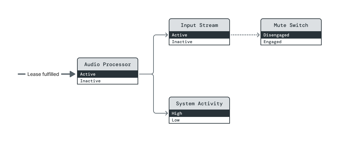 Initially, a lease on (Audio Processor, Active) holds all managed elements at
elevated power levels.
Initially, a lease on (Audio Processor, Active) holds all managed elements at
elevated power levels.
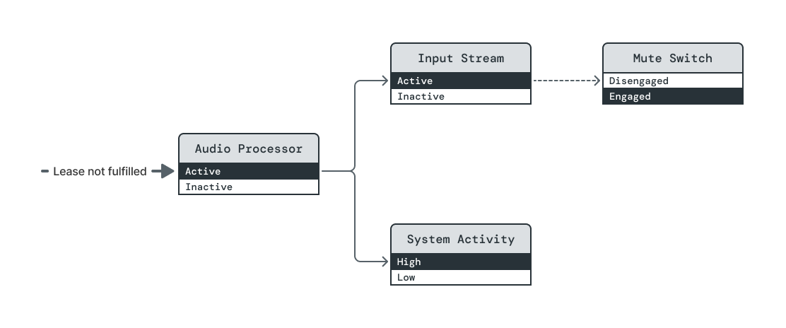 The mute switch is toggled, and Mute Switch's power level is immediately
changed to disengaged. The dependencies of both (Input Stream, Active) and
(Audio Processor, Active) are now broken.
The mute switch is toggled, and Mute Switch's power level is immediately
changed to disengaged. The dependencies of both (Input Stream, Active) and
(Audio Processor, Active) are now broken.
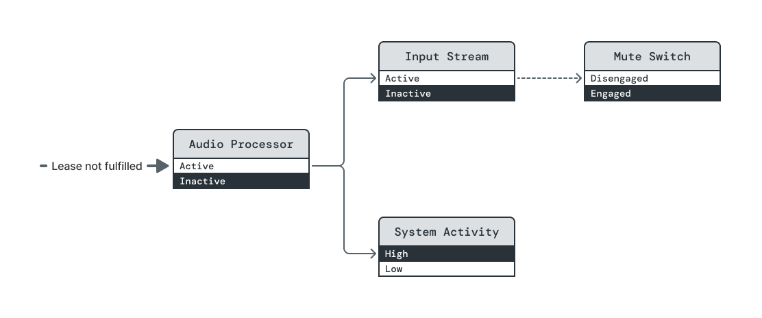 Power Broker immediately drives both Input Stream and Audio Processor to their
Inactive power levels. There is no specified ordering because both elements'
Active power levels already have unsatisfied dependencies.
Power Broker immediately drives both Input Stream and Audio Processor to their
Inactive power levels. There is no specified ordering because both elements'
Active power levels already have unsatisfied dependencies.
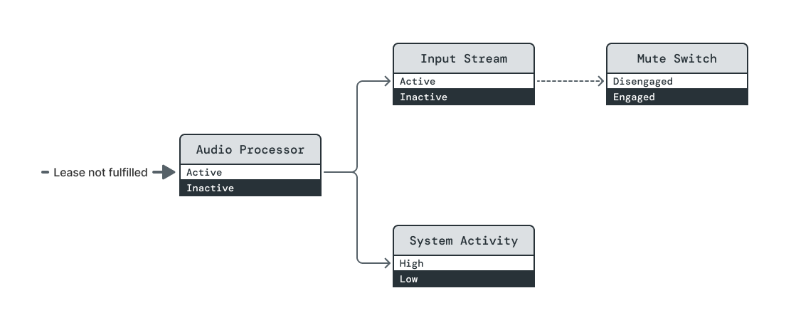 With Audio Processor's dependency no longer holding it Active, System Activity
is transitioned to Inactive.
With Audio Processor's dependency no longer holding it Active, System Activity
is transitioned to Inactive.
Opportunistic dependency on a managed element
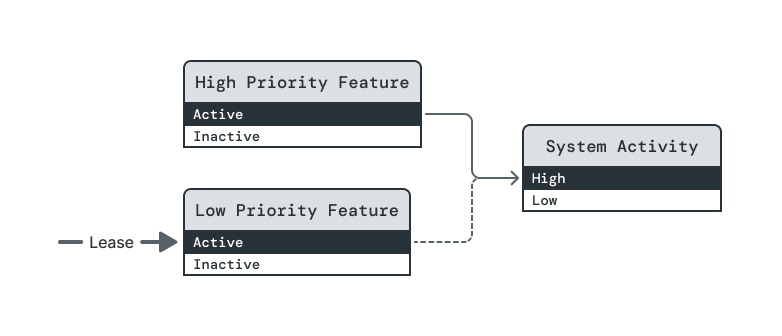
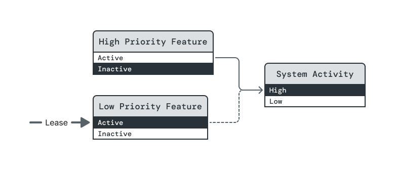
In this example, two features require the System Activity element to be at its High level in order to run. High Priority Feature's dependency is assertive, so System Activity will be raised to High if required by a lease on (High Priority Feature, Active). But Low Priority Feature's dependency is opportunistic, so it can only be raised to Active once a lease on High Priority Feature raises System Activity to High.
Steps:
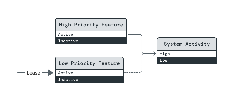
There is a lease on (Low Priority Feature, Active), but Power Broker will not satisfy it because the dependency on (System Activity, High) is opportunistic.
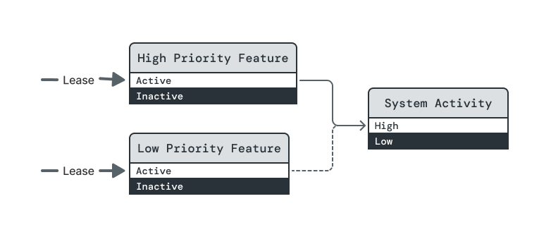
A lease is taken on (High Priority Feature, Active). This changes the steady state.
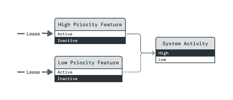
System Activity is raised to High.
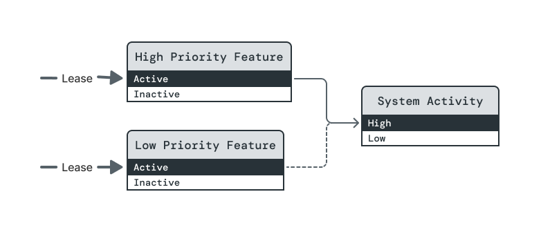
In no particular order, both feature levels are raised to Active, fulfilling both leases.
The lease on (High Priority Feature, Active) is dropped. In the new steady state, the lease on (Low Priority Feature, Active) will no longer be fulfilled.
High Priority Feature is lowered to Inactive. (Note: This RFC does not guarantee that this state change happens before Low Priority Feature's level is reduced.)
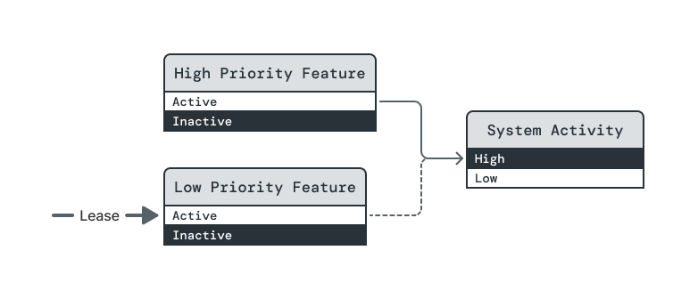
To maintain orderliness, System Activity remains High until Low Priority Feature is lowered to Inactive. This step highlights a property of opportunistic dependencies that many people find surprising. Opportunistic dependencies differ from assertive dependencies in how they are fulfilled, but Power Broker treats both dependency types equally when ensuring orderliness of power-down sequences.

System Activity is finally reduced to Low.
Error state elements
An element owner can model error states by using an unmanaged element that inhibits the operability of certain power levels. The diagram below illustrates two possible error elements for an element E with levels L0, L1, L2, L3.

In the top scenario, the error element's levels mirror E's directly. If current_level(Error State)=="Li OK", then Li is the maximum level at which E can operate. In the bottom scenario, a more concise error element inhibits E's operation at L2 or L3 if current_level(Error State)==Error.
This mechanism only serves to disable a contiguous block of levels at the top of an element's schema. It is possible to use other mechanisms to disable levels above which at least one level remains operable, but we would like to carefully examine use cases as they arise.
Attribution
Power Broker will support the attribution of current power levels to the leases that they fulfill. Should it prove useful to do so, Power Broker will support differentiation between leases that assertively require a given level and those that opportunistically require it.
Observability
Power Broker will expose information about power elements, including their power level schemas and their dependencies, via Fuchsia's established diagnostic facilities. It will furthermore maintain a record of leases and power level transitions over some suitable, likely configurable lookback window. Altogether, this information will facilitate inspection of the topology's state at the time of a query, while also enabling future tooling to provide playback of the topology's recent history.
Configuration
Many aspects of the power topology are straightforward to capture by static configuration. For example, the USB example presented earlier via diagram could instead be described as follows:
    [
        {
            name: "USB Bus",
            levels: ["Off", "On"],
        },
        {
            name: "USB Device",
            levels: ["Off", "On"],
            dependencies: {
                "On": ("USB Bus", "On")
            },
        }
    ]
Additional complexity arises when elements must be identified across component boundaries. Techniques for making static configuration straightforward will be investigated in cooperation with the Component Framework team.
Future topics
Transition latency support
In the longer term, the power topology is intended to provide a framework for understanding and optimizing the latencies of system state transitions. Power element definitions will establish a canonical location to encode expectations for local transition latencies, i.e. the time required to change an element's level once all dependencies are satisfied. Local element latencies will not be required, but they can be added as a given system matures.
Applications of local latencies include:
- Semi-static analysis (e.g. by capturing the topology configuration at runtime) of latencies of composite operations that span many elements.
- Runtime tracking of observed latencies and reporting on departures from expectations.
- Reporting of latency estimates to clients to support operations with aggressive timing requirements.
Other types of states and dependencies
Power levels and the type of dependencies we have introduced are a useful starting point for representing element states for a variety of reasons. They provide a way to capture dependencies between significant numbers of states in ways that aggregate rather than requiring cumbersome repetition. They furthermore can be utilized in a way that is conflict free -- a property that cannot be expected in all circumstances but should be utilized wherever possible.
As the power topology evolves, it may be useful and/or necessary to support other kinds of states and dependencies. For example:
- A sensor's firmware might be implemented to support a set of disjoint operating modes, each of which is optimized to satisfy different requirements, but which do not abide by a scale of strictly increasing functionality and power use. While such a sensor might be described by one binary power element for each mode, we might instead introduce a new type of state schema that can describe all modes simultaneously while including rules to resolve conflicts between competing clients.
- Some types of hardware, like GPUs, may have their power levels chosen based on simultaneous load requirements of multiple clients. It might be possible for the power topology to support dependencies that capture such load requirements and accumulate them in generic ways.
Such developments are speculative at this time; they should be revisited as necessary throughout initial subsystem integrations with the power topology.
Implementation
Implementing the power topology itself and utilizing it throughout Fuchsia is a large undertaking. There are several centralized pieces of work that will be widely used and therefore will require significant refinement past their initial implementations. Meanwhile, Fuchsia subsystems have had modest support for power management to date, and in many cases their developers will need develop appropriate power management strategies concurrent with mapping those strategies onto the power topology.
It is helpful to think of the development strategy in distinct phases, some of which are historical. In Phase 1, core functionality was developed in relative isolation, followed by a small number of integrations in Phase 2 to demonstrate key use cases and enable end-to-end testing of system suspend/resume. Equipped with the learnings first two phases, we are now laying a foundation in Phase 3 that will enable more integrations and lead to a stable development cycle as described in Phases 4+.
Phase 1 (historical): Core functionality
- Power Broker administers the power topology.
- System Activity Governor defines and administers elements that support system suspend/resume operations.
- Driver Framework supports integration of drivers with Power Framework. (Power Framework capabilities will be routed to non-driver components via standard means, requiring no special support.)
Phase 2 (historical): Proof-of-concept Power Framework integrations
- Initial integration with a driver that places hardware in lower- and higher-power states.
- Initial integration with a driver that supports a wake source.
- First usage in end-to-end suspend/resume workflows.
Phase 3 (current at time of writing): Scale-up
- Ratify this RFC; propose and ratify RFCs for Power Broker, System Activity Governor, and Power-Aware Drivers.
- Characterize design constraints imposed by existing implementations, such as effective rate limits imposed by latency overhead.
- Scope and design next set of subsystem integrations with Power Framework.
- Develop and document best practices and design patterns.
- Identify and implement small-scale improvements to assist with integrations (e.g. API improvements, straightforward optimizations).
- Establish testing procedures and support libraries that incorporate domain-specific concerns of Power Framework.
Identify highest priorities for larger-scale feature additions and improvements. Possibilities might include:
- Support for tracking transition latencies.
- Performance improvements that require significant interface changes and/or backend implementation work.
- Streamlined Component Framework integration.
Phase 4+: Further integrations and larger-scale improvements
- Integrate further subsystems.
- Optimize existing integrations where appropriate.
- Continue making small-scale improvements based on emerging needs.
- Address highest-priority larger-scale improvements.
- Identify larger-scale improvements, if any, to address in the next phase.
Performance
Many aspects of performance will be a most appropriate to address in the Phase 3 RFCs, with Power Broker's being related most closely to this proposal's conceptual buildup. However, in the current scope we can lay out some general guidelines for thinking about performance implications.
Local versus non-local performance
There is tension between the local and non-local performance requirements, as negotiating state changes with a Power Broker will generally incur at least some cost that could be avoided by a purely localized solution. However, purely localized solutions do not adequately support the systems-level analysis needed to perform effective non-local optimization.
Identification of latency overhead
Power Broker's administration of the power topology will incur a certain amount of latency overhead, particularly due to IPCs between element owners and the broker. It will be important, however, to think critically about what cost is truly overhead. Of particular note, some subsystems will inherently require communication between their processes to implement any form of power management, and integration with the power topology may accomplish that communication indirectly through Power Broker.
Size-driven latency overhead
Latency overhead due to operations like systemwide suspend and resume that are relatively infrequent will primarily be impacted by the size of the subgraphs that they affect. It will be important to understand the impact of subgraph breadth, depth, and node count on such overhead.
QPS-driven latency overhead
The primary driver of QPS to Power Broker is currently expected to be due to suspend-blocking leases; the relevant power elements will be detailed in the System Activity Governor RFC.
There is not yet a clear requirement for QPS that Power Broker must support. Rather, some subsystem integrations might find themselves needing to block suspension due to events that arrive at a sufficiently high rate that per-event leases incur too much overhead. In such situations, alternative design patterns must be pursued that consolidate the processing of multiple events under a single suspend-blocking lease.
To aid in such assessments, estimation of per-lease latency overhead will be important.
Security considerations
Security should be considered in detail for the Phase 3 RFCs, where proposals closer to concrete implementations will offer better-scoped discussions. Here we outline the security issues that are inherent in any use of the power topology.
Power dependencies and capabilities
Because the power topology uses dependencies to raise power elements to higher power levels, the ability to declare dependencies on a particular power element is itself a privileged operation. As such, to conform to Fuchsia's security model, dependency declaration should explicitly be capability-guarded at a fairly granular level, at least per-element.
Thus far, Power Broker has adopted a centralized rights-management approach to rigorously handle permissions based on currently-supported capability types. This approach was chosen as a measured decision to more quickly enable a full understanding of the power topology's implications than a concurrent evolution of Component Framework will allow. In the longer term, Component Framework may be able to represent capabilities associated with the power topology more naturally, alleviating Power Broker of some security-related responsibilities and supporting a smoother developer experience.
Risks of central administration
The use of Power Broker as a central administrator exposes it to risks such as DDoS attacks, which might prevent it from administering system-critical state transitions, and circumventions of its permissions logic, which might give an attacker the ability to manipulate hardware states maliciously.
Privacy considerations
As detailed subsystem states will be tracked on-device, it will be important to determine how to respect privacy concerns while leveraging this data in fleet metrics. This issue will be most effectively considered in Phase 4 or after, once we can concretely demonstrate data that Power Broker might export for a significant number of subsystems.
Testing
Phase 1 has incorporated unit testing of all functionality developed, as well as integration testing for Power Broker with fake clients and integration testing coupling Power Broker with System Activity Governor.
Phase 2 has added end-to-end suspend/resume testing and support for non-hermetic driver tests against System Activity Governor.
Phase 3 will establish formal support, through libraries and documentation, for testing integrations with the Power Framework in various use cases encountered in practice, while also extending coverage of end-to-end testing.
Documentation
This RFC serves as the source of truth for conceptual definitions in the power topology.
Documentation will be added to address, non-exhaustively:
- Readability-optimized descriptions of the concepts defined here.
- An integration guide.
- Examples of real power topology integrations.
- Suggested usage patterns for power elements.
Drawbacks, alternatives, and unknowns
Drawbacks
The two primary costs associated with this proposal are:
- The implementation of Power Broker. At time of writing, Power Broker has a functioning implementation with only minor deviations from the concepts presented here, so this cost is small.
- Diffuse costs for client integrations. We will investigate ways to reduce these costs via documentation, client libraries (with attention to the FIDL rubric's caveat), and testing support.
Alternatives
Decentralized power control
As an extreme alternative to the power topology, one might consider a system with no centralized power management. On such a system, subsystems would provide custom interfaces with which they may be driven into different power states.
For any systemwide mode that requires subsystems to be in particular power states, some "mode controller" entity would need to be responsible for ensuring that each subsystem is placed in an appropriate power state for that mode. That entity would need to utilize each subsystem-specific interface.
The entity responsible for controlling power state for a given mode effectively performs centralized power management for that mode, so this approach is not truly decentralized. Meanwhile, requiring the mode controller to control each subsystem using an interface of its own choosing creates an obvious scaling problem. These factors combined lead us to an expectation that Fuchsia must support at least some form of centralized power management with some degree of interface standardization.
Notably, this proposal does not take a hard stance on the extent to which subsystems should utilize the power topology. Some subsystem developers may find it most appropriate to perform light integrations that only expose one or two overarching subsystem states to the power topology as necessary to integrate with system mode transitions. Others may find it worthwhile to utilize deeper integrations that thoroughly model a subsystem throughout the platform and drivers.
Operation sequencing
An alternative to the state- and dependency-based approach we have proposed is
to standardize the sequencing of particular operations, essentially generalizing
the notion of drivers having "suspend callbacks" and "resume callbacks" as
necessary to create a working system. In Linux
suspend/resume, this takes the form of four
possible driver callbacks for suspend (prepare, suspend, suspend_late,
suspend_noirq) and four for resume (resume_noirq, resume_early, resume,
complete).
We opted against this approach for a number of reasons:
It may hide what states devices are in during the system's suspended state or in its resumed state; the process of exposing such states translates largely to creation of the topology proposed here. Furthermore, such states may be dependent on how the device is expected to behave while it is suspended.
It invites confusion as to whether "suspend" and "resume" describe actions being performed on any given device or on the system as a whole.
It is brittle to unanticipated requirements, as evidenced by the
_late/_earlyand_noirqcallback variants above.The problem of orderly dependency management is applicable to any form of power state control, not just to systemwide suspend and resume operations.
The graph of inter-state dependencies still exists in the abstract when taking the operation-sequencing approach, but it is implicit in source code.
Imperative power-down
As an alternative to on-demand utilization, the Power Framework could utilize a model of imperative power-down, in which power elements default to high-power states and must be explicitly commanded to lower ones. This approach simplifies the implementation of certain functionalities in the short term, but it more vulnerable to the introduction of untracked dependencies. It additionally does not naturally support attribution.
Meanwhile, the on-demand utilization model can accommodate imperative power-down in certain scopes if needed. In the specifics of the power topology, all that is needed is a consumer element whose purpose is to pull a resource to its desired default power level, with the consumer's owner providing an interface to change the level as needed. The consumer element can then be used to explicitly represent the use of imperative power-down in a system-level view.
Deferred topics
The following issues and questions will be addressed in the Power Broker RFC:
- Lifetime durations of elements and dependencies.
- Lease lifecycle.
- API versioning issues regarding power level definitions, based on guidance in compatibility proposal, pending update resulting from 2024-04-22 discussion.
- Does Power Broker provide any feedback to the holder of a pending lease?
- Testing guidelines for subsystems integrating with the topology, particularly regarding usage of a fake Power Broker versus real Power Broker with fake power elements.
- API for atomic addition/removal of dependencies.
- Handling of redundant dependencies.
- Behavior on crash of Power Broker.
- Behavior on crash of element owner, including comparison to graceful shutdown/startup.
- Error-handling.
Prior art and references
Linux
- Device Power Management Basics
- Evolution of Suspend-to-Idle Support in the Linux Kernel
- sysfs Power Interface
- Device Links
Mac OS
Windows