
Overview
This guide explains how to add composite nodes to the Driver Framework using composite node specifications. It assumes familiarity with the following:
Creating composite nodes
Composite nodes are nodes with multiple parents. To create a composite node, you need to:
- Define a composite node specification in a driver
- Create a composite driver with bind rules that match the specification
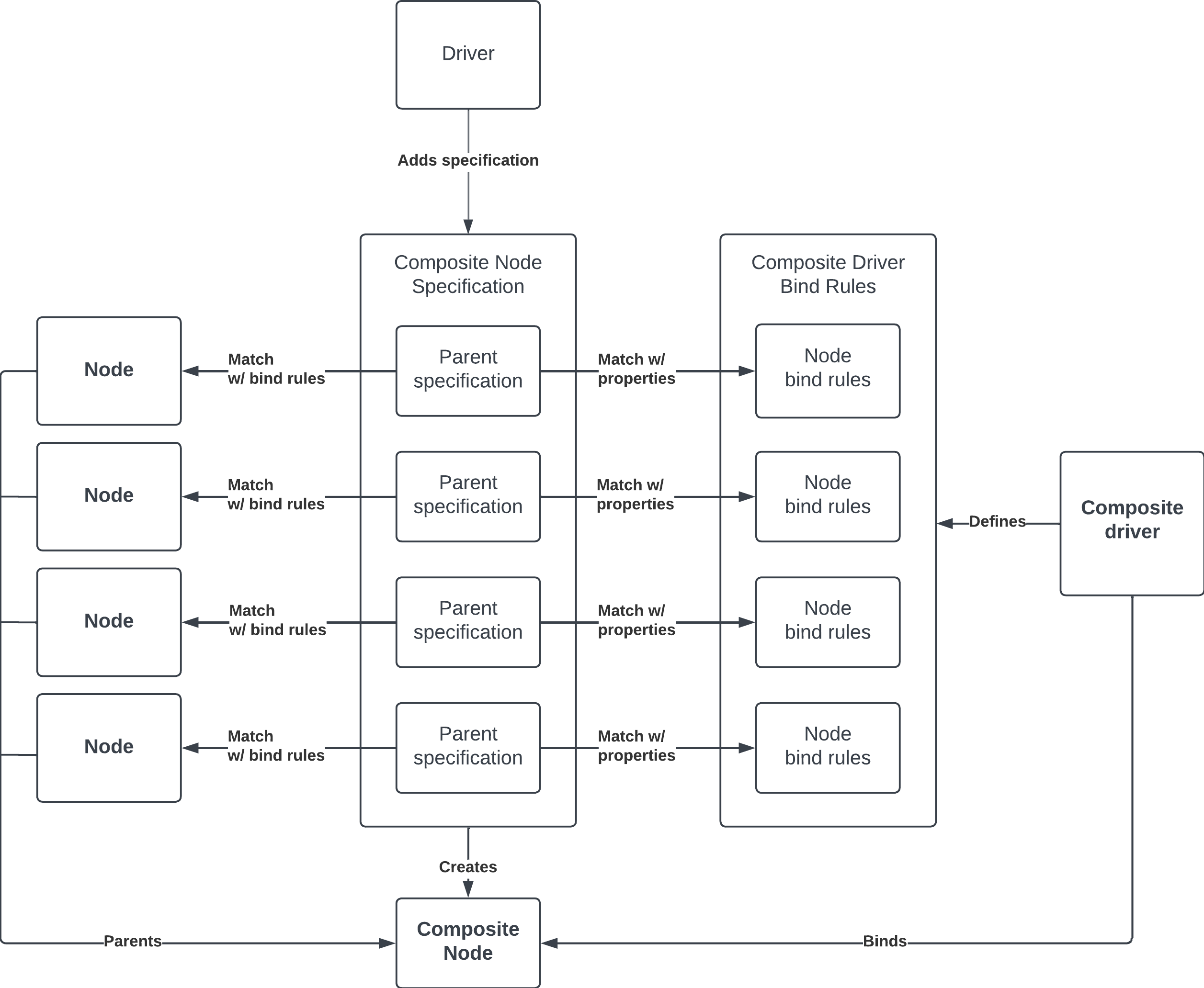
When a driver defines a specification, the process is as follows:
- The driver manager asks the driver index to find a composite driver that matches the specification
- Once a matching composite driver is found, the driver manager finds a node in the topology that matches each parent specification. Each matching node becomes a parent of the composite node.
- After all parent specifications have a match, the driver manager creates a composite node with the nodes as parents, and binds the composite driver to it. The primary node and node names are provided by the composite driver.
Defining a composite node specification
A composite node specification is a set of parent specifications that define the nodes that will parent the composite node. Each parent specification contains the following:
- Bind rules - The bind rules for matching the parent specification to a node.
- Properties - The properties in the parent specification for matching against a composite driver's bind rules. They follow the same format as node properties.
Bind rules
The bind rules are used to find and match nodes to the parent specification. The node properties are evaluated against the bind rules and if they match, the node becomes a parent of the composite.
The bind rules for parent specifications consist of a list of accepted and rejected property values. To match to the bind rules, the node properties must contain all the accepted node property values and not any of the rejected ones.
For instance, if a parent specification contains the bind rules:
- Accept
fuchsia.BIND_PROTOCOLvalues 15 and 17 - Reject
fuchsia.BIND_PLATFORM_DEV_VIDvalues "Intel"
Then a device binds to the node if it contains a value of 15 or 17 for the
fuchsia.BIND_PROTOCOL property and it doesn't contain a "Intel" value for
fuchsia.BIND_PLATFORM_DEV_VID property.
Determining the bind rules
The process for figuring out what the bind rules should be is the same as the bind rules in the bind language. To determine the bind rules, you first need to find the properties of the node that you want to bind to.
You can use the command ffx driver list-devices -v to print the properties of
every node in the node topology:
Name     : i2c-1-56
Topo Path: sys/platform/i2c-0/aml-i2c/i2c/i2c-1-56
Driver   : fuchsia-boot:///#driver/i2c.so
Flags    : MUST_ISOLATE | BOUND
Proto    : ZX_PROTOCOL_I2C (24)
3 Properties
[ 1/  3] : Key fuchsia.BIND_I2C_BUS_ID        Value 0x000001
[ 2/  3] : Key fuchsia.BIND_I2C_ADDRESS       Value 0x000038
[ 3/  3] : Key "fuchsia.hardware.i2c.Service" Value "fuchsia.hardware.i2c.Service.ZirconTransport"
From the dump, the node properties are:
fuchsia.I2C_BUS_ID= 0x01fuchsia.I2C_ADDRESS= 0x38fuchsia.hardware.i2c.Service= fuchsia.hardware.i2c.Service.ZirconTransport
The property values can be searched through bind libraries (for example, the bind libraries in src/devices/bind). In this example. since the node is an I2C node, the property values are found in fuchsia.i2c.bind.
fuchsia.i2c.bind
extend uint fuchsia.BIND_I2C_BUS_ID {
  I2C_A0_0 = 0,
  I2C_2 = 1,
  I2C_3 = 2,
};

extend uint fuchsia.BIND_I2C_ADDRESS {
  BACKLIGHT = 0x2C,
  ETH = 0x18,
  FOCALTECH_TOUCH = 0x38,
  AMBIENTLIGHT = 0x39,
  AUDIO_CODEC = 0x48,
  GOODIX_TOUCH = 0x5d,
  TI_INA231_MLB = 0x49,
  TI_INA231_SPEAKERS = 0x40,
  TI_INA231_MLB_PROTO = 0x46,
};
We also generate bind libraries from FIDL libraries, which is where the entry for
fuchsia.hardware.i2c.Service and its value fuchsia.hardware.i2c.Service.ZirconTransport
comes from. See
generated-bind-libraries
for more info.
This lets us remap the node properties to:
fuchsia.hardware.i2c.Service=fuchsia.hardware.i2c.Service.ZirconTransportfuchsia.BIND_I2C_BUS_ID=fuchsia.i2c.BIND_I2C_BUS_ID.I2C_2fuchsia.BIND_I2C_ADDRESS=fuchsia.i2c.BIND_I2C_ADDRESS.FOCALTECH_TOUCH
The bind library values can be accessed in the driver source code through its generated libraries. See the bind libraries codegen tutorial for more information.
We can define the following bind rules to match to these properties:
accept fuchsia.hardware.i2c.Service { fuchsia.hardware.i2c.Service.ZirconTransport }
accept BIND_I2C_BUS_ID { fuchsia.i2c.BIND_I2C_BUS_ID.I2C_2 }
accept BIND_I2C_ADDRESS { fuchsia.i2c.BIND_I2C_ADDRESS.FOCALTECH_TOUCH }
Writing in Driver Framework v1 (DFv1)
In DFv1, composite node specifications are written using the DDK. The functions
to write the bind rules are in
composite-node-spec.h.
With the DDK library and bind libraries codegen values, we can write the
following:
const ddk::BindRule kI2cBindRules[] = {
    ddk::MakeAcceptBindRule(bind_fuchsia_hardware_i2c::SERVICE,
                            bind_fuchsia_hardware_i2c::SERVICE_ZIRCONTRANSPORT),
    ddk::MakeAcceptBindRule(bind_fuchsia::I2C_BUS_ID,
                            bind_fuchsia_i2c::BIND_I2C_BUS_ID_I2C_2),
    ddk::MakeAcceptBindRule(bind_fuchsia::I2C_ADDRESS,
                            bind_fuchsia_focaltech_platform::BIND_I2C_ADDRESS_TOUCH),
};
Writing in Driver Framework v2 (DFv2)
In DFv2, composite node specifications are written for
composite_node_spec.fidl
in the fuchsia.driver.framework FIDL library. The
composite_node_spec.h
library in sdk/lib/driver/component/cpp can be used to simplify defining the
bind rules.
Using that library and bind libraries codegen values, we can write the following:
auto i2c_bind_rules = std::vector {
    MakeAcceptBindRule(bind_fuchsia_hardware_i2c::SERVICE,
                       bind_fuchsia_hardware_i2c::SERVICE_ZIRCONTRANSPORT),
    MakeAcceptBindRule(bind_fuchsia::I2C_BUS_ID,
                       bind_fuchsia_i2c::BIND_I2C_BUS_ID_I2C_2),
    MakeAcceptBindRule(bind_fuchsia::I2C_ADDRESS,
                       bind_fuchsia_focaltech_platform::BIND_I2C_ADDRESS_TOUCH),
};
Properties
The properties are key-value pairs that are used to match the parent specification to the composite driver’s bind rules. They are the same thing as node properties, so they follow the same format. The property key can be integer-based or string-based while the property value can be an integer, boolean, string or enum type.
Writing in Driver Framework v1 (DFv1)
In DFv1, composite node specifications are written using DDK and the functions
to write the bind rules are in
composite-node-spec.h.
With the DDK library and bind libraries codegen values, we can write the
following:
const device_bind_prop_t kI2cProperties[] = {
    ddk::MakeProperty(bind_fuchsia_hardware_i2c::SERVICE,
                      bind_fuchsia_hardware_i2c::SERVICE_ZIRCONTRANSPORT),
    ddk::MakeProperty(bind_fuchsia::I2C_ADDRESS,
                      bind_fuchsia_focaltech_platform::BIND_I2C_ADDRESS_TOUCH),
};
Writing in Driver Framework v2 (DFv2)
In DFv2, composite node specifications are written for
composite_node_spec.fidl
in the fuchsia.driver.framework FIDL library. The
node_add_args.h library in
//sdk/lib/driver/component/cpp can be used to simplify defining the bind
rules.
auto i2c_properties[] = std::vector {
    ddk::MakeProperty(bind_fuchsia::I2C_ADDRESS,
                      bind_fuchsia_focaltech_platform::BIND_I2C_ADDRESS_TOUCH),
};
Adding a composite node specification
Creating a composite node specification involves defining and adding a set of parent specifications to the driver manager.
Platform bus composite
If the composite node needs a parent from a node on the
platform bus
then the
board driver
can add the composite node
specification through the
platform_bus.fidl
API. This applies to both DFv1 and DFv2.
/// Adds a composite node specification to the bus. This will add a platform device specified
/// by |node| and insert a node into the composite node specification that matches the device.
AddCompositeNodeSpec(struct {
    node Node;
    spec fuchsia.driver.framework.CompositeNodeSpec;
}) -> () error zx.Status;
The platform bus API uses the same CompositeNodeSpec struct defined in
composite_node_spec.fidl.
See
Defining composite node specifications with FIDL
for instructions.
For example, say we defined the following composite node specification:
auto bind_rules = std::vector{
    driver::MakeAcceptBindRule(bind_fuchsia_hardware_i2c::SERVICE,
        bind_fuchsia_hardware_i2c::SERVICE_ZIRCONTRANSPORT),
    driver::MakeAcceptBindRule(bind_fuchsia::I2C_ADDRESS,
        bind_fuchsia_i2c::BIND_I2C_ADDRESS_BACKLIGHT),
};

auto properties = std::vector{
    driver::MakeProperty(bind_fuchsia_hardware_i2c::SERVICE,
        bind_fuchsia_hardware_i2c::SERVICE_ZIRCONTRANSPORT),
    driver::MakeProperty(bind_fuchsia::I2C_ADDRESS,
        bind_fuchsia_i2c::BIND_I2C_ADDRESS_BACKLIGHT),
};

auto spec = std::vector{
    fuchsia_driver_framework::ParentSpecification{
        .bind_rules = bind_rules,
        .properties = properties,
    },
};
Once the composite node specification is defined, the board driver can connect
to the platform bus through the PlatformBus FIDL protocol and use the client
end to call AddCompositeNodeSpec().
The AddCompositeNodeSpec() call inserts a parent specification for a platform
device created from the data in the node field into the given composite node
specification and then adds the modified composite node specification into the
Driver Framework. It then creates and adds the platform device.
fpbus::Node dev;
dev.name() = "backlight";
dev.vid() = PDEV_VID_TI;  // 0x10
dev.pid() = PDEV_PID_TI_LP8556; // 0x01
dev.did() = PDEV_DID_TI_BACKLIGHT;  // 0x01

auto endpoints =
    fdf::CreateEndpoints<fuchsia_hardware_platform_bus::PlatformBus>();
if (endpoints.is_error()) {
    return endpoints.error_value();
}

fdf::WireSyncClient<fuchsia_hardware_platform_bus::PlatformBus> pbus =
    endpoints->client;
auto result = pbus.buffer(arena)->AddCompositeNodeSpec(
fidl::ToWire(fidl_arena, dev),
fidl::ToWire(fidl_arena, spec), false);

if (!result.ok()) {
    zxlogf(ERROR, "AddCompositeNodeSpec request failed: %s",
               result.FormatDescription().data());
    return result.status();
}
After AddCompositeNodeSpec() is called, the following composite node
specification is added to the Driver Framework:
Name      : backlight
Driver    : fuchsia-boot:///#meta/ti-lp8556.cm
Nodes     : 2
Node 0    : None
  3 Bind Rules
  [ 1/ 3] : Accept "fuchsia.BIND_PLATFORM_DEV_VID" { 0x000010 }
  [ 2/ 3] : Accept "fuchsia.BIND_PLATFORM_DEV_PID" { 0x000001 }
  [ 2/ 3] : Accept "fuchsia.BIND_PLATFORM_DEV_DID" { 0x000001 }
  3 Properties
  [ 1/ 3] : Key "fuchsia.BIND_PLATFORM_DEV_VID"   Value 0x000010
  [ 2/ 3] : Key "fuchsia.BIND_PLATFORM_DEV_PID"   Value 0x000001
  [ 3/ 3] : Key "fuchsia.BIND_PLATFORM_DEV_DID"   Value 0x000001
Node 1    : None
  2 Bind Rules
  [ 1/ 2] : Accept "fuchsia.hardware.i2c.Service" { "fuchsia.hardware.i2c.Service.ZirconTransport" }
  [ 2/ 2] : Accept "fuchsia.BIND_I2C_ADDRESS"     { 0x00002C }
  2 Properties
  [ 1/ 2] : Key "fuchsia.hardware.i2c.Service" Value "fuchsia.hardware.i2c.Service.ZirconTransport"
  [ 2/ 2] : Key "fuchsia.BIND_I2C_ADDRESS"     Value 0x00002C
}
The first parent specification is inserted by AddCompositeSpec() and matches
the platform device, which contains bind rules and properties from the VID, PID,
and DID provided in fpbus::Node dev. The remaining parent specifications are
from the passed in composite node specification.
Driver Framework v1 (DFv1)
In DFv1, a driver can add composite node specifications through the DDK library
through the DdkAddCompositeNodeSpec() function.
The driver must first define a CompositeNodeSpec in the spec.h library. Using
the above bind rules and properties, we can define a CompositeNodeSpec with an
I2C parent specification:
const ddk::BindRule kI2cBindRules[] = {
    ddk::MakeAcceptBindRule(bind_fuchsia_hardware_i2c::SERVICE,
                            bind_fuchsia_hardware_i2c::SERVICE_ZIRCONTRANSPORT),
    ddk::MakeAcceptBindRule(bind_fuchsia::I2C_BUS_ID,
                            bind_fuchsia_i2c::BIND_I2C_BUS_ID_I2C_2),
    ddk::MakeAcceptBindRule(bind_fuchsia::I2C_ADDRESS,
                            bind_fuchsia_focaltech_platform::BIND_I2C_ADDRESS_TOUCH),
};

const device_bind_prop_t kI2cProperties[] = {
    ddk::MakeProperty(bind_fuchsia_hardware_i2c::SERVICE,
                      bind_fuchsia_hardware_i2c::SERVICE_ZIRCONTRANSPORT),
    ddk::MakeProperty(bind_fuchsia::I2C_ADDRESS,
                      bind_fuchsia_focaltech_platform::BIND_I2C_ADDRESS_TOUCH),
};

auto spec = ddk::CompositeNodeSpec(kI2cBindRules, kI2cProperties);
Any additional nodes can be added with the AddParentSpec(). For instance, if
we want to add a parent specification for a GPIO interpret pin, we can write the
following:
const ddk::BindRule kGpioInterruptRules[] = {
    ddk::MakeAcceptBindRule(bind_fuchsia::PROTOCOL,
                            bind_fuchsia_gpio::BIND_PROTOCOL_DEVICE),
    ddk::MakeAcceptBindRule(bind_fuchsia::GPIO_PIN,
                bind_fuchsia_amlogic_platform_s905d2::GPIOZ_PIN_ID_PIN_4),
};

const device_bind_prop_t kGpioInterruptProperties[] = {
    ddk::MakeProperty(bind_fuchsia::PROTOCOL,
                      bind_fuchsia_gpio::BIND_PROTOCOL_DEVICE),
    ddk::MakeProperty(bind_fuchsia_gpio::FUNCTION,
                      bind_fuchsia_gpio::FUNCTION_TOUCH_INTERRUPT)};

desc.AddParentSpec(kGpioInterruptRules, kGpioInterruptProperties);
Metadata can be passed to the composite node specification’s composite through
the set_metadata() function.
Once the CompositeNodeSpec is ready, you can add it with
DdkAddCompositeNodeSpec():
auto status = DdkAddCompositeNodeSpec("ft3x27_touch", spec);
Since CompositeNodeSpec follows the builder pattern, this can be simplify to:
auto status =
     DdkAddCompositeNodeSpec("ft3x27_touch",
          ddk::CompositeNodeSpec(kFocaltechI2cRules, kFocaltechI2cProperties)
              .AddParentSpec(kGpioInterruptRules, kGpioInterruptProperties)
              .set_metadata(metadata);
Driver Framework v2 (DFv2)
In DFv2, we use the CompositeNodeManager from the fuchsia.driver.framework
FIDL API to add a composite node specification.
@discoverable
protocol CompositeNodeManager {
    /// Add the given spec to the driver manager.
    AddSpec(CompositeNodeSpec) -> () error CompositeNodeSpecError;
};
Defining composite node specifications with FIDL
The CompositeNodeSpec struct is defined in
composite_node_spec.fidl.
You can use the spec.h
and node_add_args.h functions
in the sdk/lib/driver/component/cpp library to define the bind rules and
properties for the parent specifications.
Using the library, we can define a composite node specification with parent specifications for an I2C node and gpio-interrupt node:
auto i2c_bind_rules = std::vector {
    MakeAcceptBindRule(bind_fuchsia_hardware_i2c::SERVICE,
                       bind_fuchsia_hardware_i2c::SERVICE_ZIRCONTRANSPORT),
    MakeAcceptBindRule(bind_fuchsia::I2C_BUS_ID,
                       bind_fuchsia_i2c::BIND_I2C_BUS_ID_I2C_2),
    MakeAcceptBindRule(bind_fuchsia::I2C_ADDRESS,
                       bind_fuchsia_focaltech_platform::BIND_I2C_ADDRESS_TOUCH),
};

auto i2c_properties[] = std::vector {
    ddk::MakeProperty(bind_fuchsia::I2C_ADDRESS,
                      bind_fuchsia_focaltech_platform::BIND_I2C_ADDRESS_TOUCH),
};


auto gpio_interrupt_bind_rules = std::vector {
    MakeAcceptBindRule(bind_fuchsia::BIND_PROTOCOL,
                       bind_fuchsia_gpio::BIND_PROTOCOL_DEVICE),
    MakeAcceptBindRule(bind_fuchsia::GPIO_PIN,
                       bind_fuchsia_amlogic_platform_s905d2::GPIOZ_PIN_ID_PIN_4),
};

auto gpio_interrupt_properties[] = std::vector {
    ddk::MakeProperty(bind_fuchsia::BIND_PROTOCOL,
                      bind_fuchsia_gpio::FUNCTION_TOUCH_INTERRUPT),
};

auto nodes = std::vector{
      fdf::ParentSpec{
          .bind_rules = i2c_bind_rules,
          .properties = i2c_properties,
      },
      fdf::ParentSpec{
          .bind_rules = gpio_interrupt_bind_rules,
          .properties = gpio_interrupt_properties,
      },
  };

auto spec = fdf::CompositeNodeSpec {.name = "fo", .nodes = nodes};
Adding the composite node specification
To add the composite node specification to the CompositeNodeManager, you need
to connect to the service:
auto client = incoming()->Connect<fdf::CompositeNodeManager>();

if (client.is_error()) {
  FDF_LOG(ERROR, "Failed to connect to CompositeNodeManager: %s",
      zx_status_get_string(client.error_value()));
  return client.take_error();
}

fidl::SharedClient<fdf::CompositeNodeManager> composite_node_manager;
composite_node_manager.Bind(std::move(client.value()), dispatcher());
Then call the API:
composite_node_manager->AddSpec(std::move(spec))
    .Then([this](
        fidl::Result<fdf::CompositeNodeManager::AddSpec>& create_result) {
            if (create_result.is_error()) {
              FDF_LOG(ERROR, "AddSpec failed: %s",
                  create_result.error_value().FormatDescription().c_str());
              return;
            }
            FDF_LOG(INFO, "Succeeded adding spec");
        });
Defining the composite driver bind rules
A composite driver is a driver that only binds to a composite node. Drivers are defined as such through their bind rules. See composite bind rules for more information.
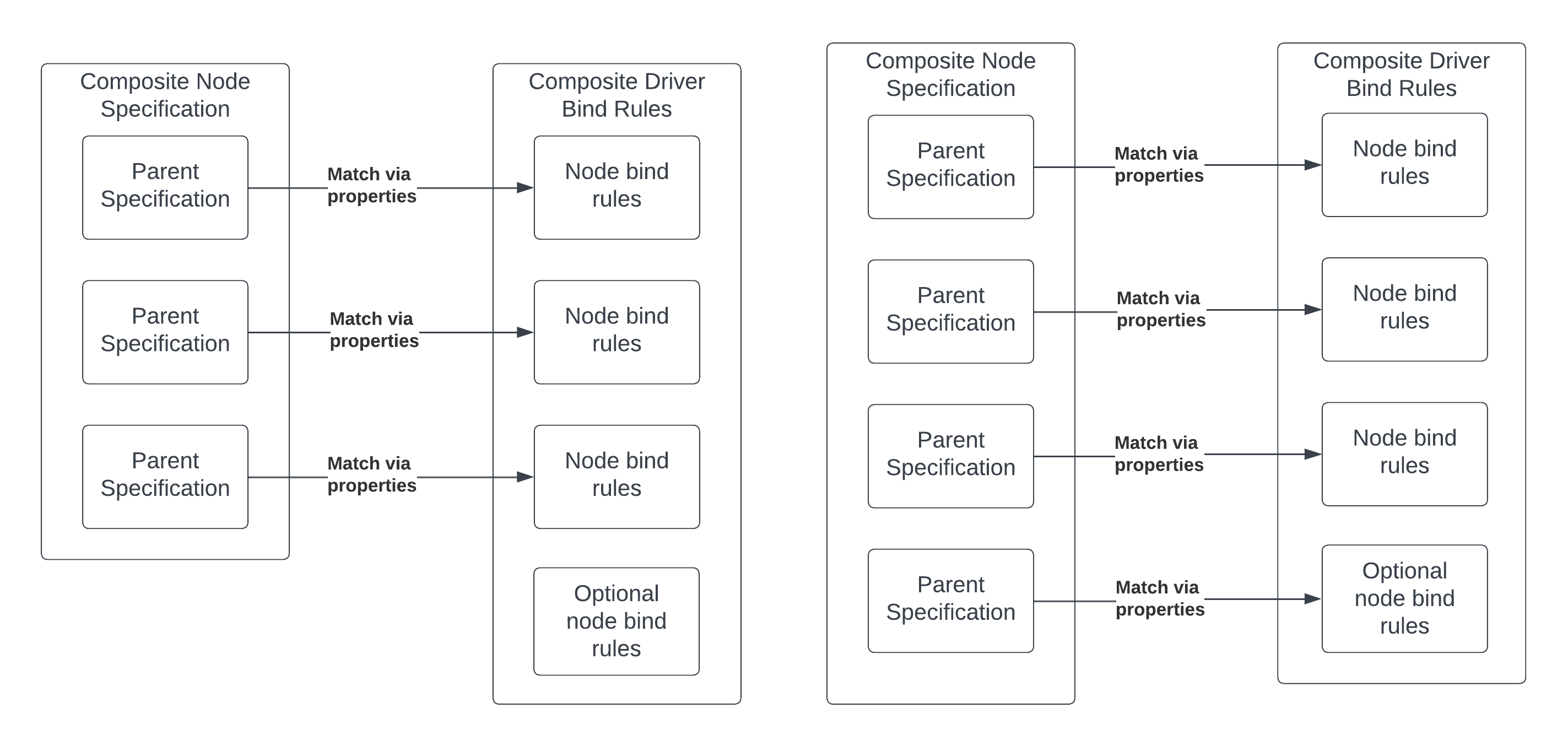
Matching process
The matching process is done by applying a composite driver's bind rules to the parent specifications' properties. A match is successful if the following is fulfilled:
- All parent specifications must match with a node in the composite bind rules
- All non-optional composite bind rules node must match with a parent specification.
Matching cannot be ambiguous:
- Each parent specification must correspond with only one composite bind rules node
- Each composite bind rule node must match with at most one parent specification. Optional bind rules may match zero parent specifications.
- Nodes do not need to be matched in order
- If an ambiguous case occurs, a warning message will be printed out.
Writing the bind rules
Given the above examples, say we want to bind to a composite node specification with the following properties in its parent specifications:
i2c parent specification properties {
     fuchsia.hardware.i2c.Service: fuchsia.hardware.i2c.Service.ZirconTransport,
     fuchsia.BIND_I2C_ADDRESS: fuchsia.focaltech.platform.BIND_I2C_ADDRESS_TOUCH,
}

gpio-interrupt parent specification properties {
     fuchsia.BIND_PROTOCOL: fuchsia.gpio.BIND_PROTOCOL_DEVICE,
     fuchsia.gpio.FUNCTION: fuchsia.gpio.FUNCTION.TOUCH_INTERRUPT,
}
We can write the composite bind rules so it’ll match the parent specification:
composite focaltech_touch;

using fuchsia.gpio;
using fuchsia.hardware.i2c;
using fuchsia.i2c;

primary node "i2c" {
  fuchsia.hardware.i2c.Service == fuchsia.hardware.i2c.Service.ZirconTransport;
  fuchsia.BIND_I2C_ADDRESS == fuchsia.i2c.BIND_I2C_ADDRESS.FOCALTECH_TOUCH;
}

node "gpio-int" {
  fuchsia.BIND_PROTOCOL == fuchsia.gpio.BIND_PROTOCOL.DEVICE;
  fuchsia.gpio.FUNCTION == fuchsia.gpio.FUNCTION.TOUCH_INTERRUPT;
}
Debugging
To verify that the composite node is successfully created and is attempting to bind the composite driver, you can look into the logs for the statement similar to:
Binding driver fuchsia-boot:///#meta/focaltech.cm
To verify that the composite node specification is added successfully and matched to a composite driver, run the command:
ffx driver list-composite-node-specs -v
This will output something similar to this:
Name      : ft3x27_touch
Driver    : fuchsia-boot:///#meta/focaltech.cm
Nodes     : 2
Node 0    : "i2c" (Primary)
  3 Bind Rules
  [ 1/ 3] : Accept "fuchsia.hardware.i2c.Service" { "fuchsia.hardware.i2c.Service.ZirconTransport" }
  [ 2/ 3] : Accept "fuchsia.BIND_I2C_BUS_ID" { 0x000001 }
  [ 3/ 3] : Accept "fuchsia.BIND_I2C_ADDRESS" { 0x000038 }
  2 Properties
  [ 1/ 2] : Key "fuchsia.hardware.i2c.Service" Value "fuchsia.hardware.i2c.Service.ZirconTransport"
  [ 2/ 2] : Key "fuchsia.BIND_I2C_ADDRESS"     Value 0x000038
Node 1    : "gpio-int"
  2 Bind Rules
  [ 1/ 2] : Accept "fuchsia.BIND_PROTOCOL" { 0x000014 }
  [ 2/ 2] : Accept "fuchsia.BIND_GPIO_PIN" { 0x000004 }
  2 Properties
  [ 1/ 2] : Key "fuchsia.BIND_PROTOCOL"        Value 0x000014
  [ 2/ 2] : Key "fuchsia.gpio.FUNCTION"        Value "fuchsia.gpio.FUNCTION.TOUCH_INTERRUPT"
If there is no matching composite driver for the composite node specification, the output will look more like:
Name      : focaltech_touch
Driver    : None
Nodes     : 2
Node 0    : None
  3 Bind Rules
  [ 1/ 3] : Accept "fuchsia.hardware.i2c.Service" { "fuchsia.hardware.i2c.Service.ZirconTransport" }
  [ 2/ 3] : Accept "fuchsia.BIND_I2C_BUS_ID" { 0x000001 }
  [ 3/ 3] : Accept "fuchsia.BIND_I2C_ADDRESS" { 0x000038 }
  1 Properties
  [ 1/ 2] : Key "fuchsia.hardware.i2c.Service" Value "fuchsia.hardware.i2c.Service.ZirconTransport"
  [ 2/ 2] : Key "fuchsia.BIND_I2C_ADDRESS"     Value 0x000038
Node 1    : None
  2 Bind Rules
  [ 1/ 2] : Accept "fuchsia.BIND_PROTOCOL" { 0x000014 }
  [ 2/ 2] : Accept "fuchsia.BIND_GPIO_PIN" { 0x000004 }
  2 Properties
  [ 1/ 2] : Key "fuchsia.BIND_PROTOCOL"        Value 0x000014
  [ 2/ 2] : Key "fuchsia.gpio.FUNCTION"        Value "fuchsia.gpio.FUNCTION.TOUCH_INTERRUPT